1.0 Leica iCON Machine Control
12d design strings and surfaces can be exported in an XML format to be directly uploaded into the Leica Icon Machine control units and Icon survey controllers without any intimidated software steps.
NOTE: This method does not apply a site calibration to the project.
If your project requires a site calibration you MUST use the Leica software to create the machine control files.
You must apply the site localisation within the UMC Software. Localisations can be imported via the XML files for Leica Users. (Contact Global Survey for help on this)
1.1 12d XML
12d has a number of inbuilt format conversions for Leica.
Using the 1200 export option, this will create an XML file and a number of different files, only XML data will be required.
Survey -> Leica
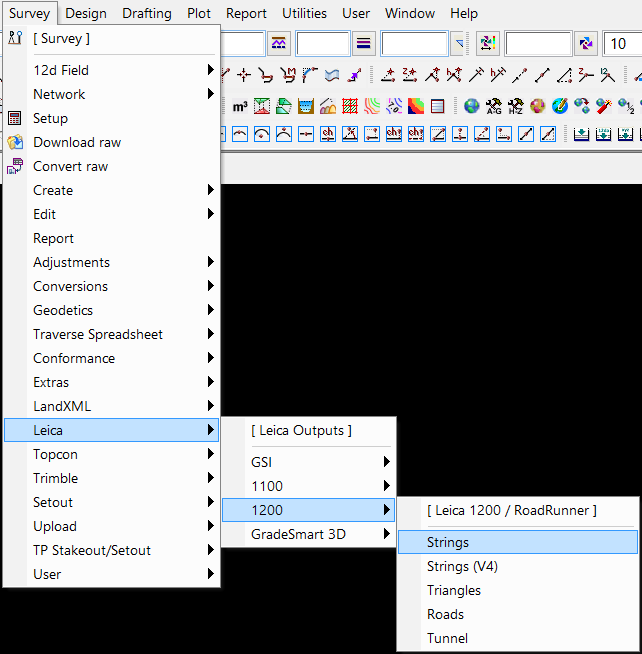
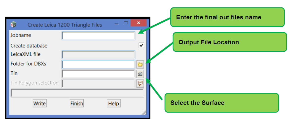
Surface Export
Survey -> Leica -> Triangles
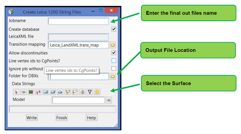
String Export
Note: Don't export the sections strings
Background Map
Export the design strings, chainages or a normal DXF, these can be used with the iCON setup to help the operator better understand the design.
2.0 Leica iCON Machine Survey Units
Create the Surface XML and background Dxf as outlined above.
2.1 Design Strings
Leica support exported design strings from 12d but within the units these are created as alignment files, which is useful for a road centre line file (so you can get chainages) or for stormwater/sewer trenches excavation.
They enable the operator to better understand the design information. It is suggested that the strings are exported as DWG file, then reimport the data into 12d, then create the XML data from the Acad data. The Leica iCON control box can use an Acad file as a background map if required.
3.0 iCON Machine Control Software
Before you can upload the information into the iCON machine control unit, a USB stick needs to have the correct files structure.
The iCON unit should create these files once inserted for the first time.
Tools -> Data Transfer
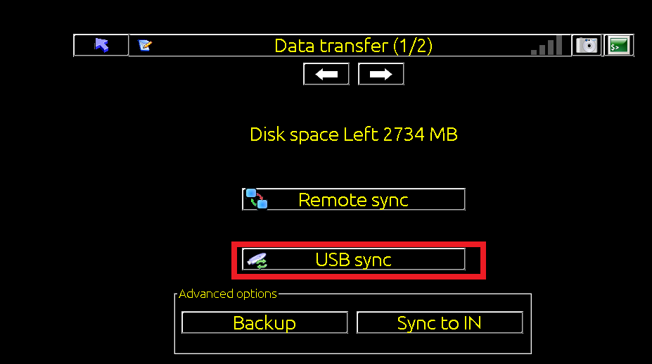
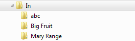
Copy the design files into the "In" folder and create a new project folder, finally paste the design files into this folder.
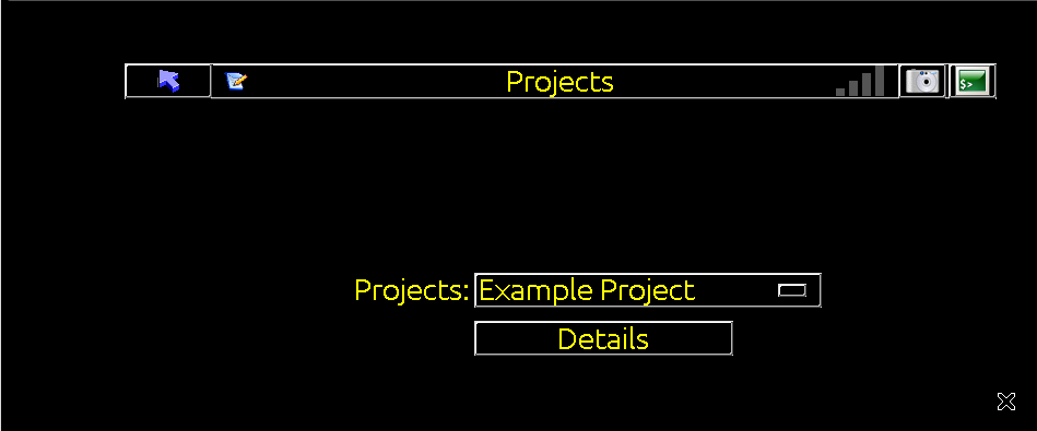
Inside the iCON Control box under Project, select the new folder.
The machine operator can take it from here.