This guide assumes that the RTK Profile, Working Style and GS connections are already configured and the Rover has an initialised position.
The internal DISTO is an optional hardware feature of the CS20 controller. It appears as a glass window at the left front of the controller.
Step 1: Calibrate the internal CS20 compass and tilt sensors
The CS20 sensor calibration is independent of the GS18T Tilt pole, which requires no calibration.
The internal Tilt sensor can be used with the internal DISTO to calculate horizontal distance and height differences to a remote point.
The internal CS20 compass can be used to measure a magnetic bearing to a remote point, which can be adjusted with a declination value to a computed grid azimuth.
- From the Home screen, select Settings from the app carousel
- Select System, then Calibrate internal sensors
- Follow the instructions
- From the Home screen, select Settings from the App carousel
- Select System
- Select Calibrate Disto tilt sensor
- Follow the instructions
If the system is subjected to a drop or hard shock, repeat the above process
Step 2: Configure the Hidden point settings
- From the Home page, select the Measure app from the app carousel
- Select Fn F6-Tools, then select Measure Hidden Point
- Select Fn F1-Settings, then Tick the box to Use a device to measure hidden points
- Connect using – Internal Disto
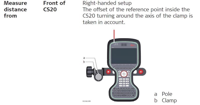
- Measure distance from
- Front or Back of CS20 are used for distances where the CS20 is held back against a feature such as a wall, or held such that the front is level with a feature such as an external corner of a wall
- Front or Back of pole are for a pole mounted CS20 in order that the distance relates to a measured location
-
Left-handed setup (Tick or leave blank), used in conjunction with Front or Back of pole allows for all combinations of pole/CS20 geometry
-
Measure azimuth using CS20 Compass allows a direct measurement of magnetic azimuth using the internal CS20 Compass.
-
Select F6-Page to access the Heights & Offsets tab
-
Compute height for hidden points. Tick the box to calculate a height for the remote point using the CS20 Tilt sensor. Make sure the Tilt sensor has been calibrated.
-
Use Distance offset. Tick and enter an offset value to be applied to the raw (slope) distance measurement
-
Use angle offset. Tick if you want to apply a declination to adjust measured magnetic north to grid north. If you do not know the declination, leave this field ticked, and a value of 0, but calculate the correction later using the calculator.
Note: local magnetic interference (e.g. buildings, parked cars) will affect the accuracy of the measured bearing. -
Use height offset – Tick if you want to determine Reduced Levels for the hidden point. Enter the height of the CS20 above the ground (measured to the centre of the CS20). Enter the target height if you cannot see the hidden point directly (for example there is vegetation around the base of a tree trunk)
-
Select F6-Page to access the Measurement quality tab
-
Enter values approximating the expected quality of the measured hidden point position and height.
-
Select F1-OK to accept the settings
Step 3: Measure Hidden Points
- Select the Method by which the hidden point will be measured
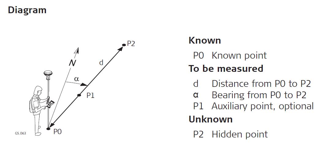
- Azimuth and Distance
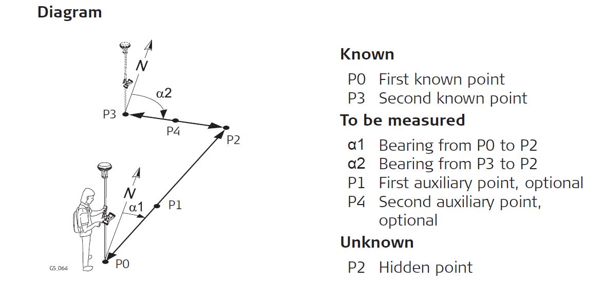
- Using 2 bearings
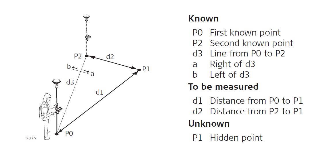
- Using 2 distances
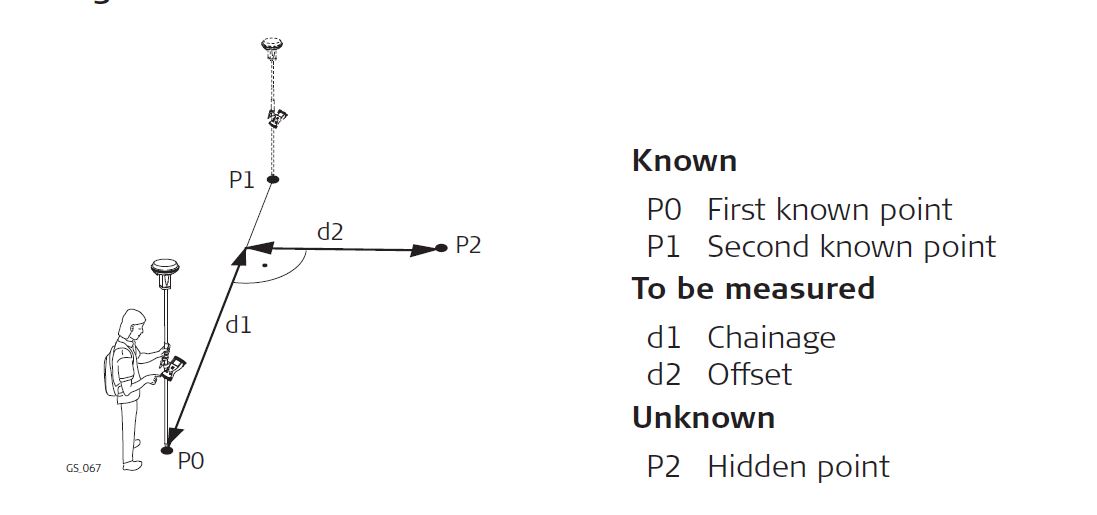
- Chainage & offset
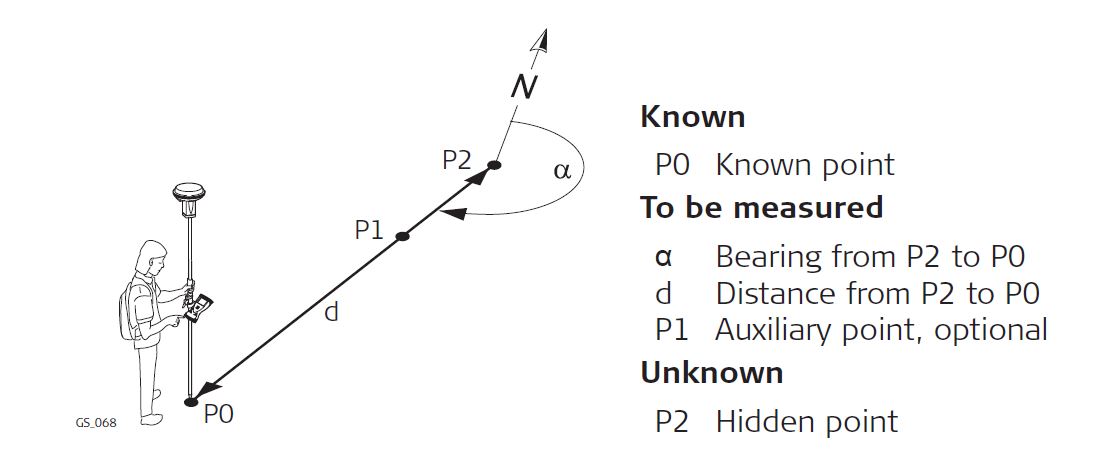
- Backwards bearing & distance
- Azimuth and Distance
- Select a point(s) from the database as a base for the calculation, or measure a new point by accessing the Measure app (F5)
-
Press F6 Page to view the Disto camera pointfinder to make sure the target is correctly located.
-
At any time, press F2 Distance to trigger a reading from the Internal Disto and populate the active measurement fields.
-
- Highlight Azimuth (for methods that require it)
-
Press F2 Distance to trigger a measurement from the Internal Disto
-
Press F3 Sun to take a grid azimuth relative to the direction of the sun
-
Press F4 Azimuth to select or measure a point that is inline towards the hidden point or away from the hidden point to serve as an azimuth reference
Note: If you do not know declination, orientate the CS20 between 2 known points, press Fn Ang Offset (F2) to Measure (F5) a magnetic bearing between the two points and calculate the angle offset between Magnetic bearing and Grid azimuth. This offset will be applied to the measured Magnetic bearing.
-
-
Highlight Horizontal Distance, or Difference in height (for methods that require it)
-
Press F2 Distance to trigger the Distance and/or height reading
-
5. Press F1 Calculate to calculate a result
6. Confirm the result’s validity
7. Press F5 Next to calculate another hidden point from the same base point(s)
8. Press F1 Store to return to the main Measure app